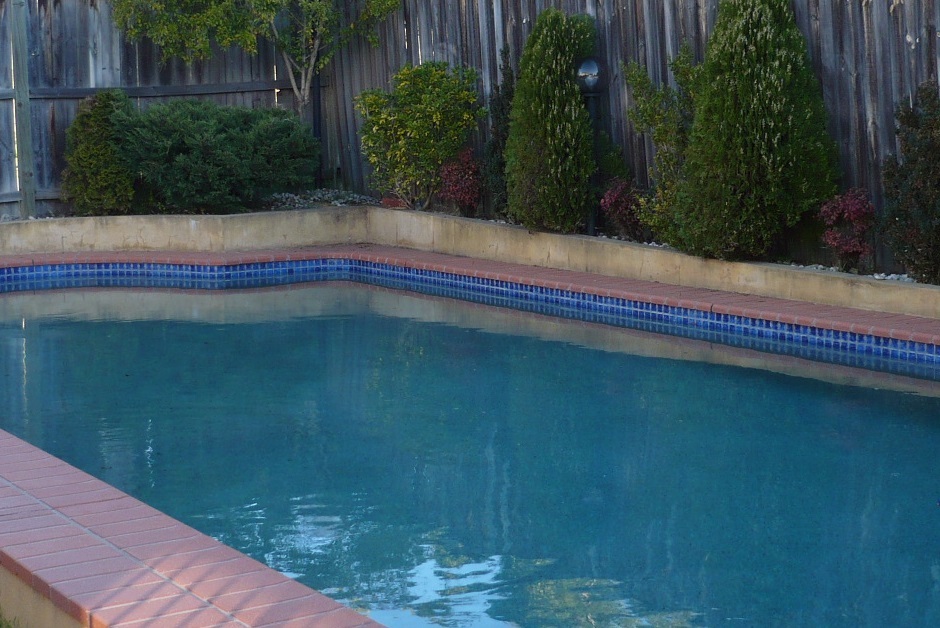
Monday 21 March 2016

Raspberry PI - Swimming Pool Solar Controller Project - Part 3


Sensor Locations 


To control the pool temperature sensors are needed. The above image shows the sensors I have installed. They are not all needed to control. I decided if I'm building my own controller then why not go all out. The middle pool and roof sensors are all I need to control and the flow was used by the old controller so I may reference that too.


Controlling Pool Pumps 


I have worked out the control logic for the pumps. 
Below I show sample code sections to give to an idea of my thinking but not the whole program. But this should be useful if you have a similar project.

Cleaning Pump Control

Cleaning/Chlorination plump needs to run AM and PM for between two and 4 hours each time depending on the time of year. 

The solution requires two schedules to do this I created an array of items as below in Schedule 1 & 2.

Schedule1=['1','06','00','On','09','00','EveryDay'] #Pump1 AM
Schedule2=['1','18','00','On','21','00','EveryDay'] #Pump1 PM


Schedule 1 array values are as follows:
Pump No 1, Start time 06:00, State On, Stop time 09:00, run every day.

The code to check the schedule against time and turn on the pump:-

PumpCMD[1] = "Off"
TimeNow = datetime.datetime.now()
SC_Start = datetime.time(int(Schedule1[1]), int(Schedule1[2]))
SC_Stop = datetime.time(int(Schedule1[4]), int(Schedule1[5]))
if ((TimeNow.time() > SC_Start) and (TimeNow.time() < SC_Stop)):
    PumpCMD[int(Schedule1[0])-1] = "On"

line 1/2 - Initial command value for the pumps is Off 
line 3 - Get the current time and date TimeNow
line 4 - Convert the Schedule1 values 1 & 2 to a start time date value
line 5 - Convert the Schedule1 values 4 & 5 to a stop time date value
lines 6/7 - If the time is between the start and stop time turn PumpCMD value On
lines 8/9 - if not turn the CMDPump off this value is used latter to turn on the pump.

Solar Pump Control

Solar pump needs to run during daylight. But it also needs the correct temperature conditions and run for a minimum of time so the pump is not damaged.

1. The system is activated between 09:00 and 20:00 to do this I used the same time control as the cleaning pump. This enables the variable SolarTimeCMD.
#Solar Pump Schedule
TimeNow = datetime.datetime.now()
SC_Start = datetime.time(int(Schedule3[1]), int(Schedule3[2]))
SC_Stop = datetime.time(int(Schedule3[4]), int(Schedule3[5]))
if ((TimeNow.time() > SC_Start) and (TimeNow.time() < SC_Stop)):
    SolarTimeCMD = True

2. Roof Temp must be 10 DGC higher than the pool temperature.(So the water will be 
heated when pumped to the roof).  
#Solar Pump variables reset
SolarReady = False
SolarRequired = False
SolarDiffOn = False
SolarPumpRunOn = False
StartSolarPump = False
RunSolarPump= False
SolarTimeCMD = False
if (Temp[1] > (Temp[3]+10)): #1=Roof Temp 3=Mid Pool Temp
    SolarReady = True

3. The Pool temperature must be below the solar setpoint
if (Temp[3] < PoolSP): #3=Mid Pool Temp
    SolarRequired = True

4. Once the pump is running it must stay on until it reaches setpoint + differential (This is to stop the pump going off and on too often and trip a breaker)
if (Temp[3] < (PoolSP + PoolSD)) and (PumpCMD[2] == "On")
    SolarDiffOn = True

5. Also it's a good idea to have a minimum pump run time of 5 minutes (Same reason as above)
if (TimeNow.time() < SolarPumpRunOnTime.time()):
    SolarPumpRunOn = True

6. If the pump is to be started the SolarpumpRunOnTime is set to current time + 5 minutes.
if (SolarTimeCMD and SolarReady and SolarRequired):
    StartSolarPump = True
    SolarPumpRunOnTime = TimeNow + datetime.timedelta(minutes = 5)

7. The CMDPump request is finally turned on if all conditions are met
if (SolarDiffOn or SolarPumpRunOn or StartSolarPump):
     PumpCMD[2] = "On"
else:
     PumpCMD[2] = "Off"

8. Latter in the code the Raspberry Pi GPIO is used to turn on a relay that starts the pump.
9. In the actual code there is also a override section to start or stop the pump regardless of the pool conditions.


Wiring and connections

The controller requires internet (Well it doesn't really need it but I wanted to connect the controller to the network and run a web site from it). The problem is WIFI does not work well through a metal shed so I had to find another way. I used PowerLine plug in modules from D-Link and they work a treat sending Ethernet over my electrical power supply.


The controller has now been installed in my pool shed. This is when I realised that having connections bottom and both sides may of been a mistake. I had to make room for the connections at the bottom. I know it looks a mess but I will refine it latter. The pumps are not connected in this picture they plug in the bottom of the unit.


Putting sensors in the pool was tricky. I used a plastic coated garden stake (Used for tomatoes) bent it 90 degrees and cable tied sensors (Water proof 10K NTC with 1.5 meter cables) to it then solders the cable to the sensors and used heat shrink to protect the connections.


This is what it looks like installed the wires and pole are held in the wall expansion then they are threaded under the bricks in a round conduit to the controller in the shed.


Monday 7 March 2016

Raspberry PI - Swimming Pool Solar Controller Project - Part 2


Project issue to be resolved in this part

The devices worked quite well but there are a few issues
1. All the wires on the soldered board were looking messy 
2. The connections are becoming a bit unreliable. 
3. Its too big for most boxes

4. The keypad and screen need mounting some how

Building a custom PCB

It became clear as I added more inputs and outputs that the board was becoming messy and was too big so I downloaded Eagle software and designed a custom PCB and got it built here it is without components.
Link to Design and make a custom PCB


I was happy with the board and soldered the components and added headers for the keyboard, real time clock, outputs and LCD display. 


Board testing success below.


All the parts required for the build laid out. I got the relays from Ebay and the power supply from Element 14. 


Now just a box to house the parts. I decided to buy this from a Jaycar shop it was a bit more expensive but I could pick it up and look at it before buying.
Power input on the left with fuse and the pump outputs at the top.


The Lid is to hold the LCD display and keypad. I could of done a better job of cutting the holes but it will be covered. 


The display, keyboard, LED's and switches installed in the lid.


The custom PCB power supply, relays and outlets installed in the box. The Raspberry PI will go on to of the main board on the left. I tried to keep the power on the right away from the electronics.


Working mounted in the box


Created a cover sheet for the lid using paper and a laminator. Now it's looking better.


Ok that works quite well but its still on my desk so more work is required.


Raspberry PI - Swimming Pool Solar Controller Project - Part 1


Project goal

1. Build a controller that will control my swimming pool's temperature using a Raspberry PI. 2. The system will need to have manual overrides for the pool pumps that anyone can use.
3. It will need to be controlled at the device with a keypad and display by anyone. 

4. The controller will need to turn on the cleaning pump by time schedule. 
4. The controller will need to turn on solar pumps by time schedule and depending of temperatures. 

External Components

Solar Panels.
Solar Pump.
Chlorination/cleaner pump.
Pool pump flow temperature sensor.
Pool Top temperature sensor.
Pool temperature sensor.
Outside air temperature sensor.
Roof temperature sensor.
Unit temperature sensor.
Internet connection for remote access.

System control components

Keypad (up,down,left, right and ok buttons).
4 x 20 LCD Display.
240 VAC supply plug for system and pump systems.
2 x 240 VAC 10 A relay outputs for the two pumps.
Override switches one for each pump (5V logic not power).
LED's for run status, pump status and alarms.
Real time clock.
Fuse 20A Slow blow (Pumps pull a large current starting)

Software requirements

1. Two start and stop schedule periods for cleaning pump.
2. One time schedule period for solar pump (Day light hours).
3. Pool temperature setpoint.
4. LCD Display and keypad with temperature and settings must be easy to use.
5. Web interface for access using mobile phone or PC.

Stage 1 - Bread board the concepts

I built a small bread board circuit of each item I needed and tested it until I was happy with the connections and operation.
3. Shift output chip for outputs - Link to Adding more outputs using the 74HC595
4. Shift input chip for the basic keypad - Link to Adding more inputs using the 74HC165
5. All of the item together

You can see a 16 x 2 LCD at the top. The sensor chip bottom left, shift output chip top right, shift input chip bottom right and a bread board keypad on the right. I was using pots for sensors.


Stage 2 - Solder on a PCB board

I then re-built the circuit on a standard PCB and soldered wires and components.


I then decided that a 20 x 4 LCD would be better. I decided that I would need to mount the LCD and keypad in the lid so I put them on ribbon cables.


The devices worked quite well but there are a few issues here
1. All the wires are starting to look messy 
2. The connections are becoming a bit unreliable. 
3. Its too big for most boxes
4. The keypad and screen need mounting some how


Tuesday 16 February 2016

Design and make a custom PCB


Converting bread board or soldered board to a printed circuit board has many benefits and a few downsides.

Advantages
  • Professional looking product
  • No ugly wires all over the place
  • Can be replicated many times
  • Can be the size and shape of your choice
Disadvantages
  • Usually have to order more than one board per design
  • Can be expensive for one board
  • If you get the design wrong the board could be scrap.
  • Can take a week or so to get the board
  • Shipping costs can be more than the price of the board (to Me in Australia)

Software for designing a custom PCB


There are a number of programs to create PBC's. I found that almost all fabrication companies accept Eagle Gerber files. So I used Eagle and there is a free version.

Eagle free version limitations are listed here http://www.cadsoftusa.com/download-eagle/freeware/  but here is the basics

  • The usable board area is limited to 100 x 80 mm (4 x 3.2 inches).
  • Only two signal layers can be used (Top and Bottom).
  • The schematic editor can only create two sheets.
  • Support is only available via email or through our forum (no fax or phone support).
  • Use is limited to non-profit applications or evaluation purposes.
Just download the software and install then click the freeware license option.


How to use Eagle


First create a new project. File -> New Project and rename it to a name of your choice.


Eagle Libraries


Next you will probably need to upload some libraries for the device that you are using. 
A good start is Sparkfun Libraries https://github.com/sparkfun/SparkFun-Eagle-Libraries 
Then for specific devices there are a lot available on Element 14 see below screen shot


There are a lot of manufacturer Eagle libraries to down load but not all each device that has a library will have link like the ones I highlighted in green boxes.


Building a Schematic


Once you have some Items you can start to build the schematic. Right click on the project and select New->Schematic 


Then minimize and go back to the main Eagle control panel and expand the libraries until you find the item you require and right click Add to Schematic.


The drawing shows the device schematic view on the left and physical view. Below the drawings is a list of connection types usually through hole and surface mount versions of the same device.
Add all the items you require then connect the items together on the Schematic. This takes some time and you should be careful to get it right. Right click gives you options and you can label wire connections. The net tool is the easiest way to connect items as you can then re-route them as required.


I recommend using headers to connect external items like LCD screens, sensors etc. This helps if you need to change connections or replace items and saves the need to re-soldering everything. 


Then check the connections with the ERC (Electrical Rule Check) tool the ERC errors will be shown. If you are happy with an error just approve it and the error will be ignored or fix the issue. I did not have a use for all the inputs one 74HC165N chip so I left them unconnected and approved these errors. 

PCB layout and wiring


Once the schematic is ready change to board view by clicking on the button from the schematic this will generate the basic PCB board and dump all the components on the page.


Move each item on to the outlined PCB. This process is a lot of trial and error so just do your best to get everything lined up where you think it will work best. Don't worry about the wiring lines the will be done automatically latter.
To move items click on the cross then move them into position right click will rotate an item if required.


Check the layout with the ERC and fix or approve any errors.
If you want wider solder traces than standard or bigger pads change settings in the DRC (Design Rules Check). The DRC will check that items are not too close together and general layout of the board. Once you have everything how you want it, use the autorouter to run all the wires. This can take some time. 


Once finished check the layout. You will probably want to reduce Vias by moving and rotating items. A via is where the connection has go Via another PCB layer to get to its destination. This below example shows some of the 75 vias that is not good.


Then move items around and find the best layout you can taking into account of mounting screws and connections. Here is the same PCB design with a better layout and just 4 vias.


I recommend using headers to connect things like LCD screens, sensors etc this means you can work on or replace the board without re-soldering everything each time. You can see that I have a header for sensor inputs, relay outputs, LCD screen, keypad, real time clock and a big one in the middle for the Raspberry PI.


Creating Gerber Files


To get a board built you will need Gerber files to send to the company that builds the boards. From the Board view click the CAM processor button.


Then from the dialog select File->Open->Job and select the gerb274x.cam


Create a folder to store the gerber files then Click on the File button on each tab and select the new folder (I add a gerber folder under the project folder) 


Check the path has changed on each tab. Click the Process Job button


Then do the same process but use the excellon.cam job and put the file in the same folder.
This will create a file for drill holes that some board manufacturers require


The files should look like the below


Then select the folder and zip the files into one file. Then check you file is good here http://www.gerber-viewer.com/default.aspx by uploading your zip file.

Now all you need to do is go to a PCB manufacturer and get your board built.

I have used http://www.seeedstudio.com/service/index.php?r=pcb the price was reasonable and they delivered the boards in about a week to Australia. I used a 2 layer board 10 cm x 10 cm there is a minimum order of 5 boards. In the US and Europe there is more choice of PCB manufacturers so you are likely to get a good price locally.


My custom PCB from .Seeed Studio


Here is the board almost fully populated with components.


Thank you for reading and I hope this information helps you build the board of your dreams.